深圳市创慧电容有限公司欢迎您!

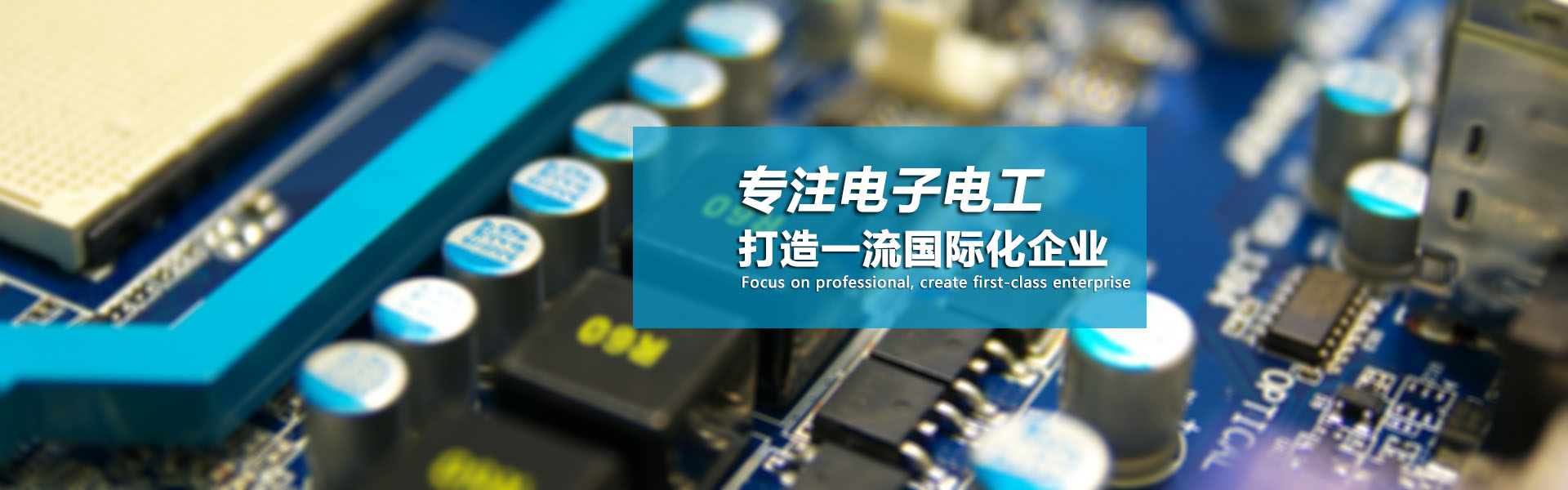
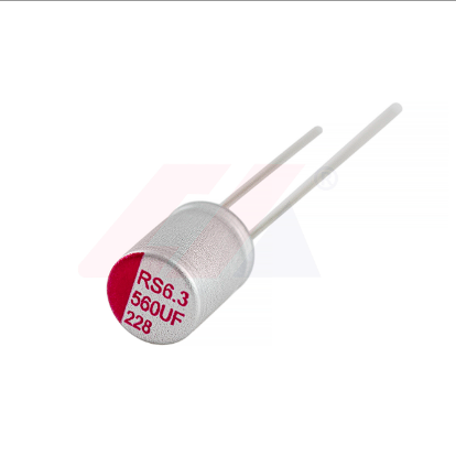
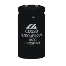
联合国内外知名机构进行产品开发,融合国际先进设计理念,加速产品创新
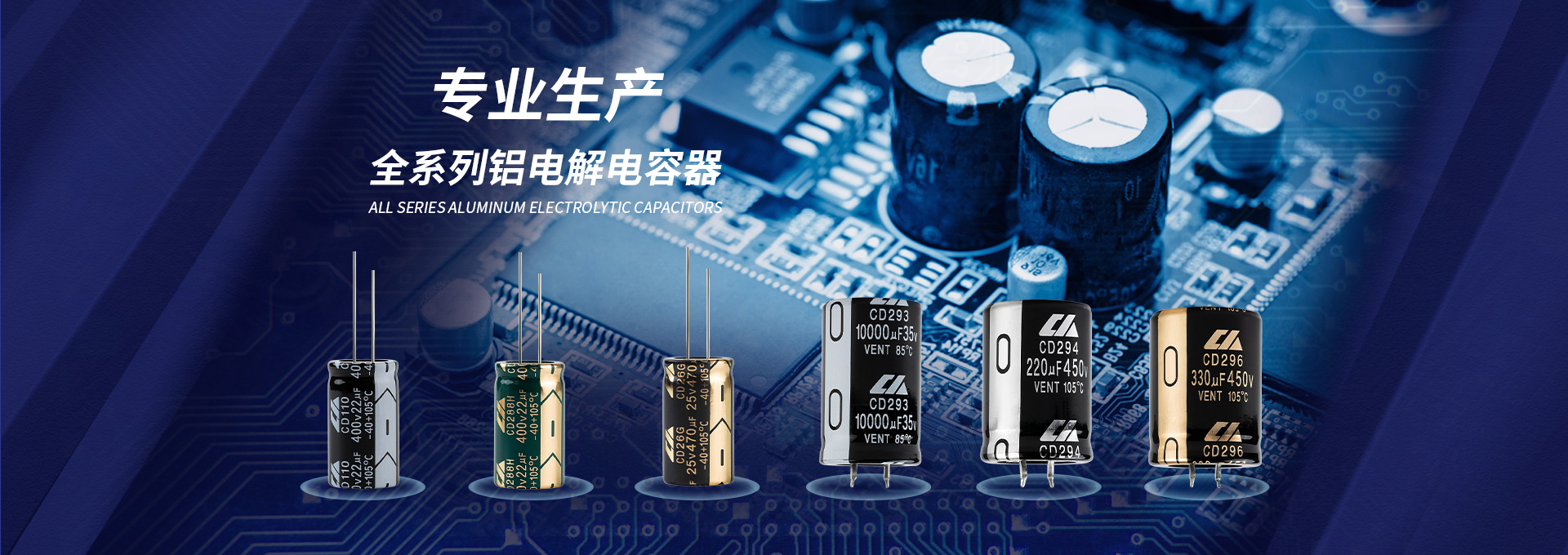
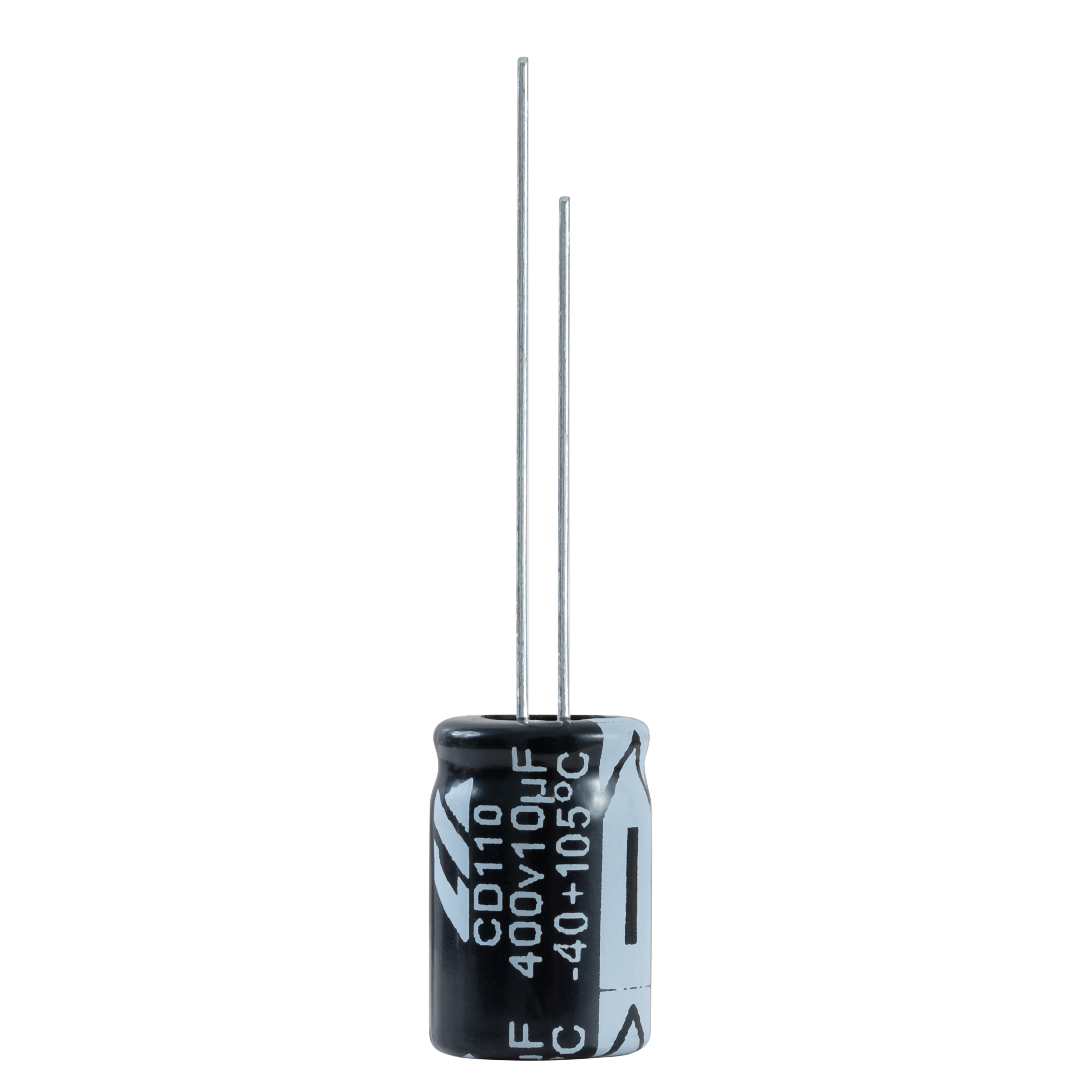
工厂拥有行业内先进的生产设备多台,满足大批量生产的需求!
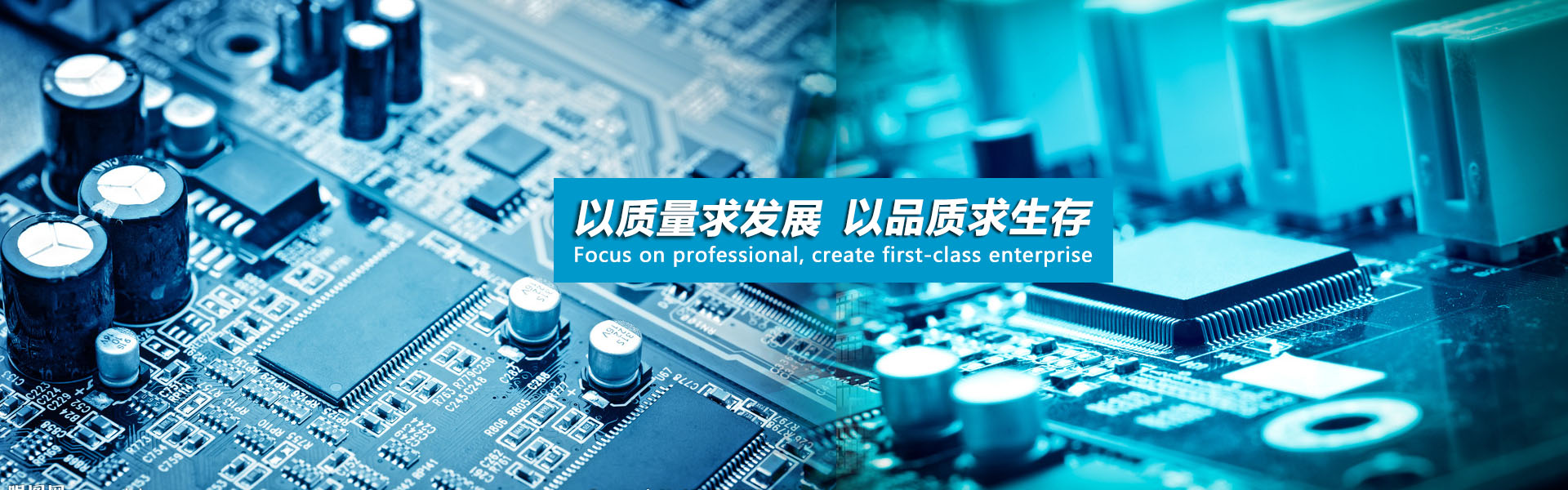
我们始终坚持以质量求发展的策略,所有产品都经过多重质量检测,严格把控质量!
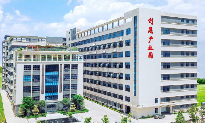
深圳市创慧电容有限公司是一家集研发设计、制造、销售、服务为一体的高科技企业,先后获得“国家高新技术企业”、“专精特新中小企业”、“市倍增企业”等荣誉称号,拥有领域内专利40余项,在行业内享有盛誉。 本公司现有自主产权生产基地创慧产业园,建筑面积达40000平方米,各类设施配套齐全,汇聚各路精英600余人。多年来,公司特别注重与国际接轨,先后借鉴国际先进的管理经验,建立了研发体系和实验室,并通过了IATF16949、ISO9001、ISO14001、QC080000体系认证。目前所有产品均通过ROHS、...
了解更多>>通过无与伦比的物理和数字检测测量连接技术的智能集成,获得一流的产品、先进的参考资料以及大量的专家协助,
解读我们周围的世界。我们与您协力
合作加快创新步伐,超越一切可能。
Copyright © 2008-2024 深圳市创慧电容有限公司 版权所有


 关注官方微信